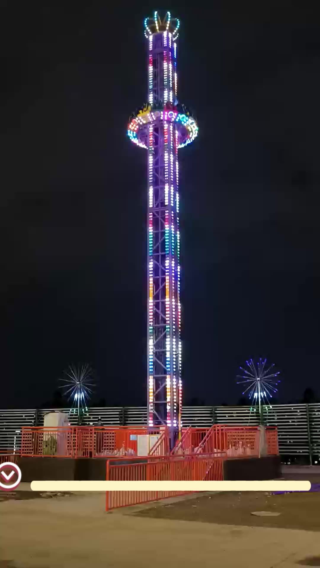
A free fall ride at an amusement park is an iconic engineering marvel that combines structural steel mechanics, pneumatic or magnetic braking systems, and rigorous compliance standards to deliver controlled, high-speed descents while balancing substantial capital and operational expenditures.
Introduction to Tall Drop Attractions
Few experiences in modern amusement parks rival the psychological intensity of a tall drop tower. Riders are slowly elevated hundreds of feet into the air, suspended for a tense moment of panoramic anticipation, and then released into a rapid descent that simulates complete weightlessness. Behind this simple, visceral thrill lies an intricate synthesis of mechanical engineering, aerospace-grade material science, advanced control automation, and complex financial modeling.
To understand how a free fall ride functions is to explore the intersection of physics and commerce. Operating a structure towering over 200 or 300 feet requires mitigating massive structural loads, executing absolute fail-safe braking geometries, and generating a continuous return on investment against staggering capital expenditures. This analysis examines the foundational engineering principles, safety compliance protocols, and economic realities that govern tall drop attractions in the contemporary global amusement industry.
Structural and Mechanical Engineering Fundamentals
The backbone of any tall drop attraction is its tower structure, which must withstand monumental static and dynamic loads. Engineers must account for dead loads (the weight of the tower, cars, and mechanical equipment), live loads (the passengers and moving carriage), and environmental loads (wind shear, seismic activity, and temperature-induced expansion or contraction).
Tower Design and Materials
Most modern tall drop towers utilize one of three structural configurations:
- Lattice Truss Towers: Constructed from interconnected galvanized steel tubing, these open-framework structures offer exceptional wind-load resistance because passing air flows through the gaps rather than pushing against a solid surface.
- Tri- or Quad-Column Tubular Masts: Sleek, enclosed steel columns that provide a modern aesthetic, often housing internal elevator lifts or counterweight systems.
- Mast-Supported Structures: Towers stabilized by external guy-wires or integrated into larger architectural complexes, though standalone structures remain the industry standard for standalone theme park installations.
Material selection prioritizes high-yield-strength structural steels (such as ASTM A572 or equivalent European standards) to prevent permanent deformation under maximum load conditions. Weld integrity undergoes rigorous non-destructive testing (NDT), including ultrasonic testing and magnetic particle inspection, to identify micro-defects before the structure is exposed to cyclic fatigue.
Carriage and Hoist Mechanisms
The vehicle—often referred to as the gondola or carriage—must ascend smoothly and lock securely before release. Historically, cable-haul systems powered by massive electric winches dominated the market. Today, many installations utilize variable-frequency drive (VFD) friction-wheel systems or high-capacity hydraulic winches.
The mechanical interface between the carriage and the vertical track relies on specialized guide rollers. These rollers are engineered with precision polyurethane tires and eccentric shafts to maintain constant, adjustable tension against the track, eliminating lateral wobble during the high-speed ascent and descent phases.
| Drive System Type | Primary Mechanism | Energy Efficiency | Maintenance Complexity |
|---|---|---|---|
| Cable-Haul Winch | Steel wire ropes, electric motor, drum | Moderate | High (frequent cable inspection/replacement) |
| Friction Drive | Motor-driven rubber tires gripping the car | High | Moderate (tire wear and alignment checks) |
| Pneumatic Cylinder | Compressed air chambers and cables | Moderate | Low-Moderate (seal and valve maintenance) |
The Physics of Free Fall and Controlled Deceleration
Despite popular terminology, true free fall—where an object is acted upon solely by gravity with zero air resistance—is rarely achieved on commercial amusement rides due to aerodynamic drag and mechanical friction. However, engineers design drop towers to closely approximate the sensation of weightlessness by matching or exceeding the acceleration of gravity ($g \approx 9.81 \text{ m/s}^2$).
Ascent, Weightlessness, and G-Forces
During the initial drop phase, gravity accelerates the car downward. If the car is simply released from rest, riders experience near-zero-g conditions because both the car and the human body accelerate at the same rate. Some modern attractions utilize a "negative-g" launch or forced-downward acceleration via pneumatic thrusters, pushing the carriage downward faster than gravity alone would dictate, creating an intensified sensation of stomach-dropping weightlessness.
Braking Technologies: Magnetic vs. Friction
The most critical engineering subsystem on a drop tower is the deceleration and braking array. A tower rising 300 feet will cause a carriage to reach speeds exceeding 60 miles per hour (approx. 96 km/h) by the time it reaches the brake zone. Engineers employ two primary braking methodologies:
- Permanent Magnetic Braking (Eddy Current Brakes): The gold standard in modern safety engineering. Copper or aluminum fins mounted on the carriage pass through permanent rare-earth neodymium magnets (or vice versa) on the tower structure. As the conductive fin enters the magnetic field, electrical eddy currents are induced, creating an opposing magnetic field that slows the car smoothly without physical contact. Because this system relies on relative motion, it requires no external power source, suffers zero mechanical wear, and provides a smooth deceleration profile regardless of weather or passenger weight.
- Friction/Mechanical Brakes: Utilizing caliper brakes clamping onto steel fins or hydraulic accumulation systems, mechanical friction brakes are frequently integrated as secondary or holding brakes. While effective, they generate heat and require regular pad replacements due to frictional wear.
Safety Systems, Redundancy, and Regulatory Compliance
Amusement park rides operate under some of the strictest regulatory frameworks in mechanical engineering. Tall drop attractions incorporate multiple layers of redundancy to ensure that a single component failure cannot result in catastrophic failure.
Restraint Systems and Interlocks
Passenger containment begins with over-the-shoulder restraints (OTSR) or ergonomic lap bars combined with interlocking shin guards. Each seat features electronic proximity sensors and mechanical ratchets. A ride control system (RCS) will not permit the tower to initiate its ascent sequence unless every single restraint sensor registers a locked status within designated millimeter tolerances.
Redundant Control Architecture
The Programmable Logic Controllers (PLCs) governing drop towers utilize fail-safe dual- or triple-modular redundant (TMR) architectures. If primary sensor data conflicts with secondary telemetry, the system automatically triggers a controlled emergency stop. Furthermore, mechanical drop-pins and safety dogs physically block the car from descending prematurely if the primary hoist mechanism loses power or tension.
Regulatory Standards
Installations must comply with rigorous international and national standards, such as:
- ASTM F24 Committee on Amusement Rides and Devices: The primary North American standard governing design, manufacturing, operation, and maintenance.
- EN 13814: The European standard specifying safety requirements for amusement rides and amusement parks.
- Local Jurisdictional Inspections: Independent third-party engineering firms and state/provincial inspectors conduct annual load testing, non-destructive crack detection, and electrical audits prior to public operation.
Economics of Tall Drop Attractions: Capital, Operation, and ROI
While engineering dictates whether a tall drop ride can exist, economics dictate whether it should be built. Tall drop towers represent significant capital investments that require careful financial forecasting and lifecycle management.
Capital Expenditure (CapEx)
The upfront cost of constructing a tall drop tower is substantial. A world-class 300-foot tower can range from $5 million to over $15 million USD, depending on structural customization, themed elements, site preparation, and foundation engineering. Deep-driven concrete pilings are often required to anchor the tower against severe wind loads, adding hundreds of thousands of dollars to civil engineering budgets before a single piece of steel arrives on site.
Operational Expenditure (OpEx) and Throughput
Operational efficiency is measured by hourly rider throughput. Drop towers face an inherent economic bottleneck: cycle times.
- Loading and Unloading: 90 to 120 seconds.
- Ascent Phase: 45 to 60 seconds (at approximately 3 to 5 feet per second).
- Drop and Brake Cycle: 10 to 15 seconds.
- Total Cycle Time: Roughly 3 to 4 minutes per batch.
To maximize revenue per hour, multi-car configurations or rotating ring-gondolas (where riders sit facing outward in a circle around a central mast) are frequently deployed to increase capacity per cycle, often accommodating 24 to 40 riders simultaneously. Maintenance overhead, while minimized by contactless eddy current brakes, still mandates daily morning safety checks, weekly NDT audits of high-stress joints, and scheduled hydraulic fluid replacements.
Return on Investment (ROI) and Landmark Value
Despite high initial costs, tall drop attractions serve a vital economic function: they act as visual anchors and marketing centerpieces for theme parks. A towering structure visible from miles away drives organic marketing, boosts season-pass sales, and increases secondary in-park spending by drawing crowds toward underutilized park zones.
Frequently Asked Questions
What happens if the power goes out while a drop tower is at the top?
Most drop towers feature uninterruptible power supplies (UPS) and backup diesel generators to safely lower the carriage via auxiliary hydraulic or manual release procedures. Furthermore, eddy current magnetic brakes operate independently of electrical power, ensuring that even in a total blackout, the car cannot crash into the ground.
How do engineers account for high winds on tall drop towers?
Towers are engineered with built-in wind-load tolerances. Anemometers mounted at the peak of the structure continuously monitor wind velocity. If sustained winds or gusts exceed safe operational thresholds (typically around 35 to 45 mph depending on design), the ride control system automatically halts operation and lowers or parks the carriage in a secure lower position.
Why do some drop towers tilt forward before dropping?
Tilting mechanisms add a psychological element of surprise and vulnerability. Mechanically, hydraulic actuators pivot the seating ring outward over empty space, shifting the center of gravity and altering the visual perspective of the rider just milliseconds before the drop mechanism engages.
How often are drop towers inspected for structural fatigue?
In addition to daily pre-opening mechanical walk-arounds and sensor checks by park technicians, certified third-party inspectors conduct comprehensive structural audits annually. These audits include ultrasonic testing, eddy current testing of welds, and load-test verifications mandated by regional safety codes.
Practical Next Steps for Park Developers and Engineers
For engineering teams, municipal planners, or amusement park developers evaluating a tall drop attraction, project execution requires a phased, multidisciplinary approach:
- Site Geotechnical Analysis: Conduct deep soil borings to determine foundation requirements for extreme wind-moment loads.
- Throughput Modeling: Calculate peak park attendance metrics to determine whether a standard single-car tower or a high-capacity rotating ring model is required to prevent excessive queue times.
- Regulatory Pre-Consultation: Engage regional safety authorities and ASTM/EN compliance auditors early in the schematic design phase to streamline eventual certification.